|

|
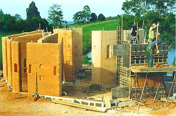
Construction FAQsWe've had many questions about the building over the years since this website began - our faq section details the main questions with our responses. |
Frequently Asked Questions concerning the Construction Process
- I was wondering why you had to raise your earth- floor up 225mm? Was dealing with local council difficult?
- I really love your earth floor. Where can I learn the process?
- How were the rafters attached at the support end?
- Did the rafters require a tension ring such as a steel cable to keep the whole from collapsing?
- How did you construct the roof in space?
- What are the main points in assembling the roof structure?
- How did you join the beams to their neighbours?
- How did you fit the beams together?
- I wish to be informed in greater detail on your reciprocal force rafter and cupola design. Please include any "mistakes" we can learn from.
I was wondering why you had to raise your earth- floor up 225mm? Was dealing with local council difficult?
Yes the local council had a requirement that floors built on the ground are 225mm above 'natural ground level'. Probably a sensible requirement for folks
building in a depression to make sure floods don't come inside - for us it was unnecessary as we are on a knoll with steep falls away in 270-degrees. However - the requirement was "in the book" and that was that as far as the building inspectors were prepared to look.
As it turned out it had an advantage in that the dwarf walls were 300mm high (the concrete bases to form the base of the earth walls) - the remaining 75mm was exactly the required exposure for a "visual termite barrier" which spared us having to use toxic soil treatments or expensive (and possibly poorly-effective) mesh barriers.
So I guess spirit knew what it was about more than we did - as usual - in fact that would be my theme for the building, whenever it seemed less than perfect, I came to understand the flaw was in my perception and - given a "couple-a-days" I would come to see the perfection (as long as I let go of the desire to "have things my way").
I really love your earth floor. Where can I learn the process?
In between the walls is the best places to learn the floors (-;. What I used was the same mix as the walls but sieved much finer - a 10mm mesh - and no
cement and a plate compactor rather than a pog rammer. The humidity needs to be much higher for the plate compactor.
Surface sealant was the same as the walls, although we applied much more to the floors than the walls.
How were the rafters attached at the support end?
a piece of 4X2 was laid (vertically) on either side of the join between the beam and the vertical support member and 2 bolts pinned them together
Did the rafters require a tension ring such as a steel cable to keep the whole from collapsing?
No - one of the beauties of this structure is the absence of lateral thrust on the supports.
How did you construct the roof in space?
The first beam rested on a strut on a platform and the each beam was fitted in place (roughly) - then moved aside so that we could
notch the supporting beam to match the underside of the one on top. This works flawlessly until the last beam which has to fit those above and below. At this point we discovered that the strut was about 15mm too low (coincidentally the depth of the notches we were cutting - hmmmmm). We also had around 3/4 tonne of timber resting on this one 4X2 (which was by that stage resembling a match-stick) on top of a pine-wood scaffold.
We eventually persuaded the thin end of a wedge between the beam and the strut and many full-blooded swings with a sledge hammer gradually persuaded the 'bottom' beam to lift enough to allow the final one into place.
This was (for me) a heart-in-the-mouth experience knowing that I was 6 metres above ground level and if anything went awry there would be me, gravity and 8 very heavy timbers dancing in mid-air.
The best was yet to come, once the final beam was in place the strut had to be removed - at this juncture I realised I had never seen this done or even spoken to anyone who had done it and all I was going on was a photo and faith.
Another full-blooded swing of the sledge removed the strut and - to my amazement - the roof beams didn't settle at all, there was no movement or sound - just sat there with a 'what was all the fuss about' and 'see, we didn't really need that strut at all' kind of feel.
And there they sit today!
What are the main points in assembling the roof structure?
The keys are:-
- take plenty of time and effort to ensure the initial supporting strut is sited so that the first beam is exactly in the right place.
- If in doubt, higher is probably better than lower.
- Make sure the prop is not sited so as to interfere with the final beam's insertion.
It would be smart to try a model first - I've seen one made of 1/4" X 7/8" X 15" slats which happily supported 2 large men (standing on a plywood disc on top) - and that is a pretty outrageous sight!
I hadn't thought much further about it but your comments on it's wider relevance are fascinating and ring true with me. I suppose it is a demonstration of 'going with the flow' rather than against it which results in much less fatigue and failure.
Unfortunately there was nowhere I found which offered any guidance - I had to work with an engineer to create plans for council approval, but the construction was 'seat-of-the-pants' stuff. These days you may find there is a lot more material on the net - google "reciprocal rafter roof" would be my suggestion.
It is a magnificent roof and far stronger (IMHO) than a conventional rafter-style one. It is far more challenging to build in that no members meet at right angles.
How did you join the beams to their neighbours?
Yes we only notched the top of the beams and the bottom support was also cut to match the under-side plane of the beam which meant we could slide the beams 'in and out' or 'up and down' (longitudinally along its major axis) to get the most out of the timber (we needed the off-cuts to fill in the spaces in the central collar and it was touch and go with the shorter ones).
Once the top notch was cut we really couldn't slide the beam any more - and here I suspect you will face another grok-challenge without a model.
These features of the roof are all inter-related in that you can't change one without affecting the others:-
- beam depth
- width (diameter) of the central opening
- pitch of the roof (and hence the angle of the notch)
How did you fit the beams together?
Yes we only notched the top of the beams and the bottom support was also cut to match the under-side plane of the beam which meant we
could slide the beams 'in and out' or 'up and down' (longitudinally along its major axis) to get the most out of the timber (we needed the off-cuts to fill in the spaces in the central collar and it was touch and go with the shorter ones).
Once the top notch was cut we really couldn't slide the beam any more - and here I suspect you will face another grok-challenge without a model.
These features of the roof are all inter-related in that you can't change one without affecting the others:-
beam depth, width (diameter) of the central opening, pitch of the roof (and hence the angle of the notch).
It does seem that you could move them in concert but in practice it wouldn't work, I think this is one of the attractions of the design flexibility of this structure in that if you have a roof pitch and an opening size, they will determine your beam depth. Alternatively if you know the beam depth and the opening size your roof pitch is determined (hope that makes sense).As to the costing - the design is so unusual (I've been told) that it is not easy to compare with other building costs - also there was 3.5 years of our unpaid efforts included and what does one cost those at? My attitude is that this will last for at least 200 years as compared with the 25-year life span of most contemporary dwellings. On that basis the cost over the life span makes this far cheaper than any other system. Ah - the joys of rationalisation (-;, still on a planetary level I feel it is a valid view.
wish to be informed in greater detail on your reciprocal force rafter and cupola design. Please include any "mistakes" we can learn from.
the roof structure is a very versatile one in that it can accommodate a range of spans, pitches and opening sizes. It is also (IMHO) one of the strongest I've known as any load on the roof is shared evenly amongst all the beams.
I originally came across the design via Findhorn - and I believe in some circles it is even known as the 'Findhorn Roof' - you may have more luck pursuing your enquiry there. These days I'd look for Reciprocal Rafter Roof.
Unfortunately I have not the time to list all the mistakes you might make as I have come to accept that there is really no limit to man's creativity when it comes to doing things differently (-;
However these might help:
the positioning of the first beam is critical, it will not become obvious that it is out-of-position until the last beam is introduced, by which time it is a real challenge to move it.
We used laminated Australian hardwood beams which are lighter than steel girders but not by much - I would investigate lighter timber if you are doing it by hand (without a crane).
Lining and cladding the structure are a challenge as there are no right-angles anywhere - choose your materials with a view to having to accommodate non-right-angled connections.
 |
return to top of this page |  |